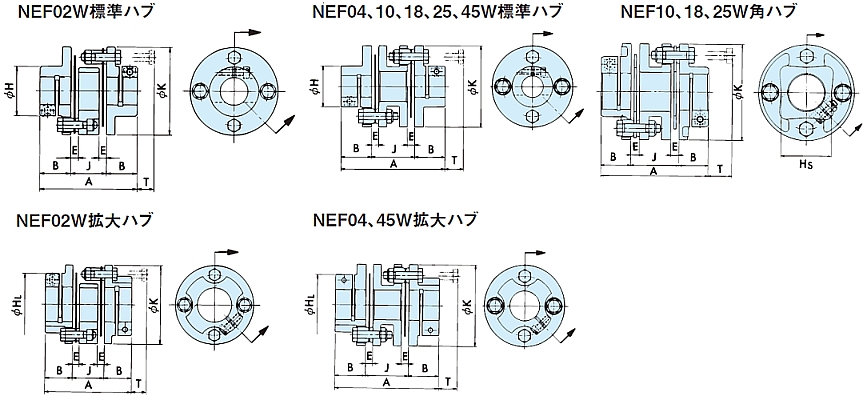
エクトフレックスカップリングNEFシリーズ主要諸元
形番:NEF18W-N19CXB32C
カタログ・取扱説明書
伝動能力・寸法表
| 許容トルク | 最高 回転速度 r/min |
標準在庫軸穴径 | 軸穴径 範囲 |
ねじり剛性 | 軸方向バネ定数 | |||
|---|---|---|---|---|---|---|---|---|
| N・m | {kgf・m} | N・m/rad | {kgf・m/rad} | N/mm | {kgf/mm} | |||
| 下表参照 | 18000 | 19,22,24,25,【28】,【30】,【32】,【35】 | 14~35 | 7.84×10⁴ | 0.8×10⁴ | 63.7 | 6.5 | |
| A | B | E | H | HL | HS | K | U | T |
|---|---|---|---|---|---|---|---|---|
| 104.4 | 28.7 | 8.3 | 51 | - | 49 | 93 | 68 | 23 |
| 許容ミスアライメント | 質量 kg |
慣性 モーメント kg・m2 |
GD2 {kgf・cm2} |
||
|---|---|---|---|---|---|
| 角度誤差 deg |
平行誤差 | 軸方向 変位 |
|||
| 2 | 0.6 | ±2.4 | 2.45(2.24) | 24.8(23.6) | 99.1(94.3) |
注)
1.最高回転速度はカップリングの伝動能力によって決められているものです。バランスの調整は施されていません。
2.標準在庫軸穴径で太字は標準ハブ、【】で囲ったものは角ハブ、数字だけのものは拡大ハブです。
3.質量、慣性モーメント、GD2は丸ハブの最大軸穴径のときの値です。( )はNEF02、04、45は拡大ハブ、NEF10、18、25は角ハブの値です。
4.許容軸方向変位は、角度誤差0のときの値です。
5.クランプ用ボルトのゆるみ止めとして角ハブタイプはUナットを使用しています。それ以外はナイロックボルトを使用しています。
6.クランプ部の伝達トルクについては表を参照してください。表にない軸穴径につきましては当社までお問い合わせください。
7.中空軸への取り付けの場合は、当社までお問い合わせください。
8.ねじり剛性はディスクのみの値です。
クランプ軸穴径とトルク
| 形番 | 軸穴径Φ mm | 15 | 16 | 17 | 18 | 19 | 20 | 22 | 24 | 25 | 28 | 30 | 32 | 35 |
|---|---|---|---|---|---|---|---|---|---|---|---|---|---|---|
| NEF18 | ボルトサイズ | M6 | M6 | M6 | M6 | M6 | M6 | M6 | M6 | M6 | M6 | M6 | M6 | M6 |
| 締付トルク N・m{kgf・m} |
13.7 {1.40} |
13.7 {1.40} |
13.7 {1.40} |
13.7 {1.40} |
13.7 {1.40} |
13.7 {1.40} |
13.7 {1.40} |
13.7 {1.40} |
13.7 {1.40} |
13.7 {1.40} |
13.7 {1.40} |
13.7 {1.40} |
13.7 {1.40} |
|
| 伝達トルク N・m{kgf・m} |
68.0 {6.97} |
83.0 {8.45} |
90.0 {9.18} |
100 {10.2} |
109 {11.1} |
113 {11.5} |
126 {12.9} |
136 {13.9} |
143 {14.6} |
176 {18.0} |
176 {18.0} |
176 {18.0} |
176 {18.0} |
ホームページからのお問い合わせ/資料請求
製品お問い合わせ
各製品へのお問い合わせ及び製品カタログ・資料請求はこちらより承っております。
ご利用の際は当サイトの会員登録をお願いします。
【お問い合わせ】 |
【資料請求】 |
|---|
各種証明書の発行について
一部の証明書は弊社製造番号と紐づけて発行しております。
以下についてはご購入先を通じてご依頼ください。
・該非判定書
・EAR判定書
・原産地証明書
見積依頼、納期確認について
弊社では直接販売をしておりません。
購入価格・納期に関するお問い合わせはお取引のある商社様を通じてご確認ください。
購入先をお探しのお客様は取扱販売店一覧をご覧ください。
お問い合わせ窓口
製品窓口
| カップリング・パワーロック | TEL : 0120-251-602 | FAX : 0120-251-603 |
|---|
月曜日~金曜日 9:00~12:00 / 13:00~17:00
(祝日・弊社休業日を除く)


