ECHT-FLEX Coupling NEF Series Major Specifications
Model No. :NEF130W-LH50JD2XKH75JD2
[Click to enlarge ]
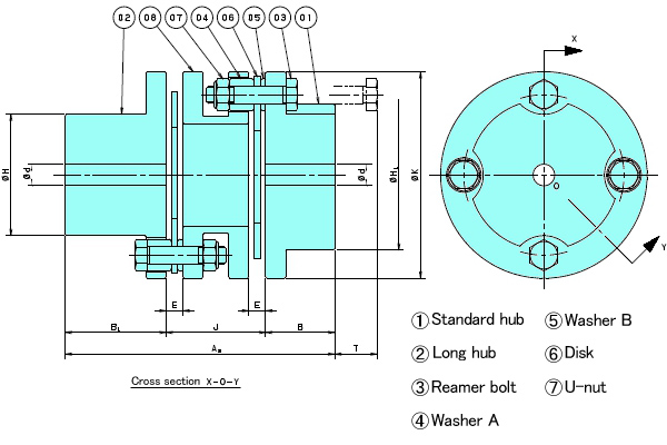
This drawing is for NEF□□W-KRXLR.
Refer to the PDF outline drawings or contact us for detail drawings.
PDF Outline Drawing
CAD data in DXF format
Contact us for details.
(Click here for a list of all DXF files )
3D CAD data
Contact us for details.
Standard Price
Contact us for details.
Delivery
Contact us for details.
Catalogs ・Instruction Manuals
- E-Book Catalog (Japanese)
- E-Book Catalog (English)
- Instruction Manuals (Japanese) (Single type / Spacer type )
- Instruction Manuals (English) (Single type / Spacer type )
- Instruction Manuals (Japanese) (Long spacer type )
- Instruction Manuals (English) (Long spacer type )
- Instruction Manuals (Japanese) (Power-Lock specifications )
- Instruction Manuals (English) (Power-Lock specifications )
- Instruction Manuals (Japanese) (Clamp fastening )
- Instruction Manuals (English) (Clamp fastening )
- Instruction Manuals (Japanese) (Taper-Lock fastening )
- Instruction Manuals (English) (Taper-Lock fastening )
Transmission Capacity and Dimensions
| Allowable Torque | Max. Rotation Speed r/min |
Plain Bore d |
Standard Stock Bore Dia. Range | Keyway Maximum Shaft Diameter Φ | Torsional Rigidity | Axial Spring Constant | |||||
|---|---|---|---|---|---|---|---|---|---|---|---|
| N・m | {kgf・m} | Standard Hubs | Long Hub | Extended Dia. Hub | N・m/rad | {kgf・m/rad} | N/mm | {kgf/mm} | |||
| 1270 | 130 | 10000 | 25 | 35~70 | 74 | 74 | 85 | 73.5×10⁴ | 7.5×10⁴ | 177 | 18.1 |
| PCD | A1 | A2 | B | BL | E | F | H | HL | J | K |
|---|---|---|---|---|---|---|---|---|---|---|
| 134 | 192.4 | 220.2 | 57.2 | 85 | 16.8 | 14 | 106 | 129 | 78 | 168 |
| Dd | N | No | Ni | T | T' | Allowable Misalignment | Mass kg |
Moment of Inertia kg・m2 |
GD2 {kgf・cm2} |
||
|---|---|---|---|---|---|---|---|---|---|---|---|
| Angular Misalignment deg |
Parallel Misalignment | Axial Displacement mm |
|||||||||
| 73 | 92 | 102 | 92 | 20 | -7.8 | 2 | 1.0 | ±5.0 | 12.2 | 447×10-4 | 1787 |
Note)
1.Refer to the Table of Dimensions for long hub and extended-diameter hub dimensions. For long hubs, the overall length will be extended for as much as dimension B is lengthened.
2.The maximum speed depends on the transmission capacity of the coupling. No balance adjustment has been conducted.
3.The weight, moment of inertia, and GD2 are given for the maximum bore diameter (keyway) for a standard hub. For extended-diameter hubs and long hubs, add the value given in the Additional GD2 Table.
4.Tsubaki can make models with non-standard spacer lengths. Refer to the page for the Long Spacer Type.
5.The allowable axial displacement is based on the assumption that the angular misalignment is 0.
6.Check that the key surface pressure is in accordance with your operating conditions. The hub is made of S45C.
Contact Information
Online Inquiries
For inquiries in English, visit the Inquiries page on our Tsubaki Group website.
