ECHT-FLEX Coupling NEF Series Major Specifications
Model No. :NEF10S-H19XH35
[Click to enlarge ]
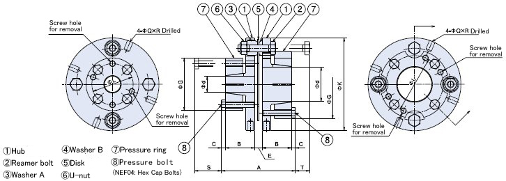
This drawing is for NEF□□S-H□□XH□□.
Refer to the PDF outline drawings or contact us for detail drawings.
PDF Outline Drawing
CAD data in DXF format
The minimum and maximum bore diameters for the applicable size are displayed.
(Click here for a list of all DXF files )
3D CAD data
Please re-set the shaft bore diameter etc. on the linked screen.
Standard Price
Contact us for details.
Delivery
Contact us for details.
| ※ | The CAD data contained herein is made available to you via the CAD drawing library; PARTcommunity is provided by CADENAS WEB2CAD Co. |
| ※ | Please direct your inquiries regarding the CAD data service or PARTcommunity to: CADENAS WEB2CAD Co. TEL: +81 (3) 5961-5031 FAX: +81 (3) 5961-5032 |
Catalogs ・Instruction Manuals
- E-Book Catalog (Japanese)
- E-Book Catalog (English)
- Instruction Manuals (Japanese) (Single type / Spacer type )
- Instruction Manuals (English) (Single type / Spacer type )
- Instruction Manuals (Japanese) (Long spacer type )
- Instruction Manuals (English) (Long spacer type )
- Instruction Manuals (Japanese) (Power-Lock specifications )
- Instruction Manuals (English) (Power-Lock specifications )
- Instruction Manuals (Japanese) (Clamp fastening )
- Instruction Manuals (English) (Clamp fastening )
- Instruction Manuals (Japanese) (Taper-Lock fastening )
- Instruction Manuals (English) (Taper-Lock fastening )
Transmission Capacity and Dimensions
| Allowable Torque | Max. Rotation Speed r/min |
Standard Stock Shaft Bore Dia. | Torsional Rigidity | Axial Spring Constant | |||
|---|---|---|---|---|---|---|---|
| N・m | {kgf・m} | N・m/rad | {kgf・m/rad} | N/mm | {kgf/mm} | ||
| 98 | 10 | 20000 | 14・15・16・17・18・19・20 22・24・25・28 30・32・35 |
8.8×10⁴ | 0.9×10⁴ | 58.8 | 6.0 |
| A | B | K | C | d | G | L | Dd | Q | R | S | T |
|---|---|---|---|---|---|---|---|---|---|---|---|
| 64.4 | 25.4 | 81 | 3.5 | 14・15・16・17・18・19・20 | 46 | 36 | 37 | 5.1 | 8 | 26 | 12.5 |
| 22・24・25・28 | 53 | 43 | |||||||||
| 30・32・35 | 60 | 50 |
| Allowable Misalignment | Mass kg |
Moment of Inertia kg・m2 |
GD2 {kgf・cm2} |
|
|---|---|---|---|---|
| Angular Misalignment deg |
Parallel Misalignment | |||
| 1 | ±1.0 | 0.9 | 7.30×10⁻⁴ | 29 |
Note)
1.The weight, moment of inertia, and GD2 are given for the maximum bore diameter.
2.The maximum rotating speed does not take dynamic balance into account.
3.Each allowable misalignment is based on the assumption that both of the other two misalignment values are zero.
4.The recommended tolerance for the mounting shaft is h7. 軸径Φ35は公差+0.010~0のサーボモータ軸にも対応しています。
5.May be used with other coupling types (keyway or clamp).
Contact Information
Online Inquiries
For inquiries in English, visit the Inquiries page on our Tsubaki Group website.
