サーボモータ用減速機 主要諸元
形番:SWJMK35E10DF-E4DC
[クリックで拡大]
※上記はイメージです。正確な情報は下記及び図面にて必ずご確認ください。
カタログ・取扱説明書
伝動能力表
| 減速比 (実減速比) |
出力軸許容トルク N・m | 許容ラジアル荷重 N | 許容アキシャル荷重 N | 許容入力 kW | 概略質量 kg |
バックラッシ 分 |
慣性モーメント ×10-4kg・m2 |
||||||||
|---|---|---|---|---|---|---|---|---|---|---|---|---|---|---|---|
| 入力回転速度 r/min | 入力回転速度 r/min | 入力回転速度 r/min | 入力回転速度 r/min | ||||||||||||
| 3000 | 2000 | 1500 | 3000 | 2000 | 1500 | 3000 | 2000 | 1500 | 3000 | 2000 | 1500 | ||||
| 10 | 12.2 | 15.7 | 19.2 | 1335 | 1504 | 1648 | 2457 | 2876 | 3249 | 0.44 | 0.38 | 0.35 | 2.9 | 40 | 0.363 |
・最高入力回転速度は3000r/minです。
・間欠運転の場合は起動時に、モータ起動トルクで加速できるかの確認が必要です。
起動時の効率は許容入力kWと出力軸許容トルクから算出できる効率の1/2の値を使用ください。
・本シリーズの許容入力を超えるサーボモータについてはSWMシリーズで特形対応しますので当社までご相談ください。
・許容入力の背景着色部は、使用するマウントコードによってはサーボモータと減速部を接続するカップリングの許容トルクを越える場合があります。
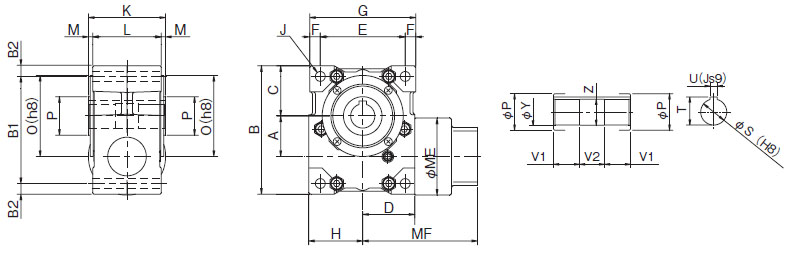
本体寸法 単位:mm
| A | B | B1 | B2 | C | D | E | F | G | MF | MG | H | J | K | L | M | O | P | Q | S | T | U | V1 | V2 | Z |
|---|---|---|---|---|---|---|---|---|---|---|---|---|---|---|---|---|---|---|---|---|---|---|---|---|
| 35 | 115 | 96 | 9.5 | 45 | 44 | 71 | 9.5 | 90 | 109 | 155 | 46 | 4-M8ボルト用貫通穴 | 70 | 65 | 2.5 | 72 | 30 | 2.5 | 20 | 22.8 | 6 | 25 | 20 | 21 |
マウント部寸法 単位:mm

| MA | MB | MC | MD | ME | ML | MS | MT | カップリング | |
|---|---|---|---|---|---|---|---|---|---|
| 形番 | 許容トルク N・m | ||||||||
| □60 | φ50G7 | M5深さ10(PCD70) | 5 | 80 | 25 | φ8 | M3 | NES70W | 7 |
ホームページからのお問い合わせ/資料請求
製品お問い合わせ
各製品へのお問い合わせ及び製品カタログ・資料請求はこちらより承っております。
ご利用の際は当サイトの会員登録をお願いします。
【お問い合わせ】 |
【資料請求】 |
|---|
各種証明書の発行について
一部の証明書は弊社製造番号と紐づけて発行しております。
以下についてはご購入先を通じてご依頼ください。
・該非判定書
・EAR判定書
・原産地証明書
見積依頼、納期確認について
弊社では直接販売をしておりません。
購入価格・納期に関するお問い合わせはお取引のある商社様を通じてご確認ください。
購入先をお探しのお客様は取扱販売店一覧をご覧ください。
お問い合わせ窓口
製品窓口
| 減速機 | TEL : 0120-251-602 | FAX : 0120-251-603 |
|---|
月曜日~金曜日 9:00~12:00 / 13:00~17:00
(祝日・弊社休業日を除く)
