フラットベヤ®主要諸元
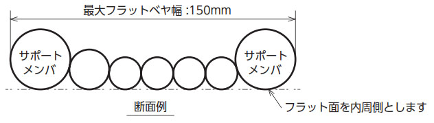
- ■サポートメンバを内蔵することでフラットケーブルに比べ、長ストロークで使用可能です。
- ■使用条件に応じた専用のケーブルやチューブを組み込んで提供します。
構造

[クリックで拡大]
カタログ・取扱説明書
材質
| サポートメンバ | エンプラ | ||||
|---|---|---|---|---|---|
| サポートメンバ用チューブ | PVC | ||||
| ストッパ | PE | ||||
基本仕様・能力

[クリックで拡大]
| 最大移動ストローク 注)1 | サポートメンバ 屈曲半径 R40 ・・・ 1600mm | ||||||
|---|---|---|---|---|---|---|---|
| サポートメンバ 屈曲半径 R70 ・・・ 2200mm | |||||||
| サポートメンバ 屈曲半径 R100 ・・・ 2800mm | |||||||
| サポートメンバ 屈曲半径 R130 ・・・ 2800mm | |||||||
| 最大移動速度 | 2m/sec | ||||||
| 最大加速度 | 4G | ||||||
| 使用温度範囲 | -10℃~80℃ | ||||||
| 最大ケーブル・チューブ外径 | 16mm以下 | ||||||
| 最大幅目安 | 150mm | ||||||
注) 1.支持物質量0.4kg/m時。
2.サポートメンバ屈曲半径とフラットベヤ設置時の屈曲半径は異なる場合があります。
選定
フラットベヤは、すべてメーカ仕様選定商品です。お問合せシートに使用条件をご記入いただき、当社まで送付ください。
当社にて仕様を選定します。
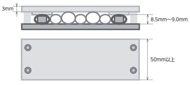
フラットベヤ固定用クランプの取扱い
ケーブル外径が8.5mm以下の場合
下図の通り、クランプ長さ50mm以上、クランプ板厚3mm以上、
クランプ内高さ8.5mm~9.0mmになるように
スペーサなどのご使用をお願いします。
またM6ボルトで4ヵ所締付けてください。

[クリックで拡大]
ケーブル外径が8.5mmより大きい場合
下図の通り、クランプ長さ50mm以上、クランプ板厚3mm以上、
サポートメンバ用チューブ部分が内高さ8.5mm~9.0mmになるように
スペーサなどのご使用をお願いします。
またM6ボルトで4ヵ所締付けてください。
[クリックで拡大]
注意事項
サポートメンバ用チューブ部分が内高さ8.5mm以下になると、サポートメンバが変形し、破損する恐れがありますので、ご注意ください。
オプション
コネクタ取付け
コネクタメーカ名、コネクタ形番、端子形番、ハーネス図面をご提示ください。当社にて対応可能かを確認し、回答します。
使用する部品は当社調達、ご支給どちらでも対応可能です。
カタログに掲載のないケーブル組込み
当社カタログに掲載のないケーブルを組込むことも可能です。当社までお問合せください。
フラットベヤ製作時の不具合を除き、ご支給いただいたケーブルは当社保証の範囲外となりますので、ご了承ください。
固定用クランプ
当社にて製作可能です。お客様で製作いただく場合、上記推奨寸法をご参考に製作してください。
ケーブル・エア配管用チューブ
300V定格ケーブル
| UL STYLE No. | 2464 |
|---|---|
| 定格温度 ℃ | 80 |
| 定格電圧 V | 300 |
| 使用温度範囲 ℃ | -10~80 |
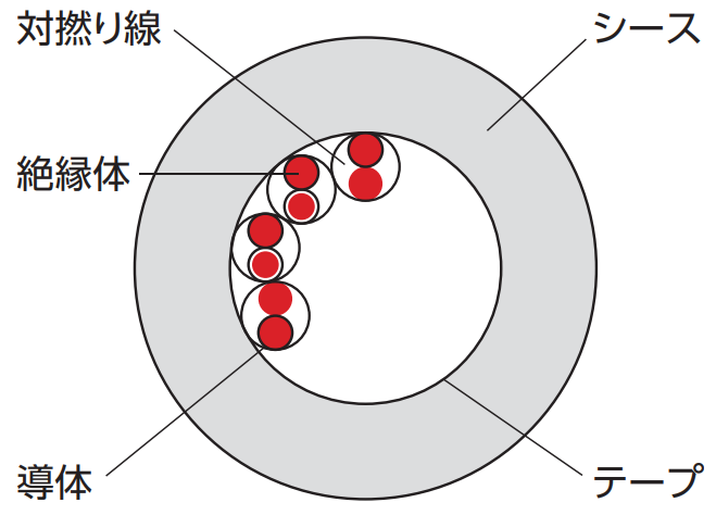
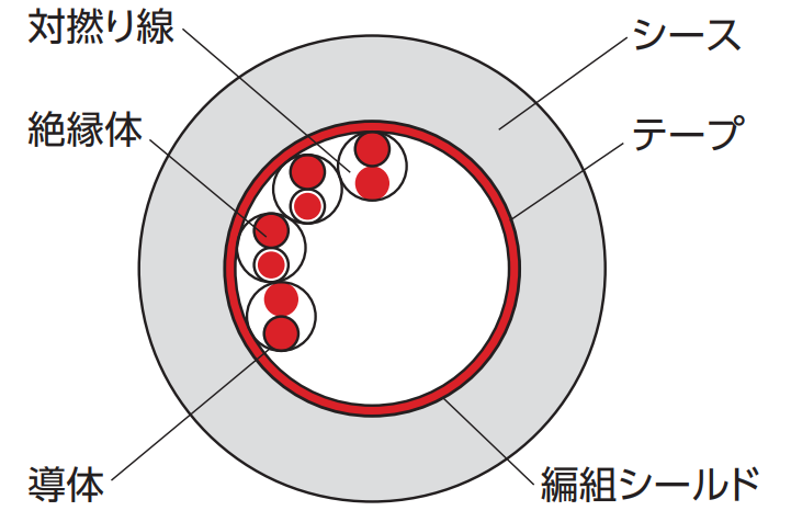
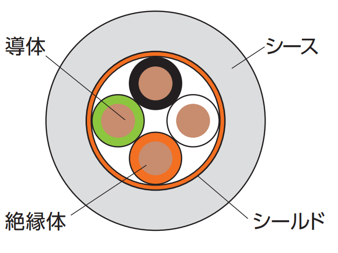
| 導体 | すずめっき軟銅撚り線 |
|---|---|
| 絶縁体 | 特殊エラストマー |
| シールド | すずめっき軟銅線 編組 |
| シース | 耐油性PVC (黒) |
| シールド有無 | 最小曲げ半径 |
|---|---|
| シールドなし | ケーブル外径の6倍以上 |
| シールドあり | ケーブル外径の8倍以上 |
| 導体 | 心線径 mm | 対数 | シールドなし | シールドあり | 許容電流 注) A (30℃) |
||||||||||
|---|---|---|---|---|---|---|---|---|---|---|---|---|---|---|---|
| SQ mm2 |
AWG サイズ |
構成 | No. | 外径 mm |
概算質量 kg/km |
概算質量 kg/m |
最小曲げ R 外径×6倍 |
No. | 外径 mm |
概算質量 kg/km |
概算質量 kg/m |
最小曲げ R 外径×8倍 |
|||
| 0.1 | 28 | 49/0.05 | 0.74 | 1 | S1 | 3.3 | 13 | 0.013 | 20 | S32 | 3.8 | 21 | 0.021 | 31 | 2.4 |
| 2 | S2 | 4.4 | 20 | 0.020 | 27 | S33 | 4.8 | 30 | 0.030 | 39 | 1.8 | ||||
| 3 | S3 | 4.7 | 23 | 0.023 | 29 | S34 | 5.1 | 34 | 0.034 | 41 | 1.6 | ||||
| 4 | S4 | 5.0 | 27 | 0.027 | 30 | S35 | 5.4 | 38 | 0.038 | 44 | 1.4 | ||||
| 5 | S5 | 5.3 | 32 | 0.032 | 32 | S36 | 5.7 | 43 | 0.043 | 46 | 1.3 | ||||
| 6 | S6 | 5.6 | 36 | 0.036 | 34 | S37 | 6.0 | 48 | 0.048 | 48 | 1.2 | ||||
| 7 | S7 | 5.6 | 39 | 0.039 | 34 | S38 | 6.0 | 50 | 0.050 | 48 | 1.2 | ||||
| 8 | S8 | 6.0 | 43 | 0.043 | 36 | S39 | 6.4 | 56 | 0.056 | 52 | 1.1 | ||||
| 10 | S9 | 6.6 | 52 | 0.052 | 40 | S40 | 7.0 | 66 | 0.066 | 56 | 1.0 | ||||
| 0.2 | 25 | 102/0.05 | 0.93 | 1 | S10 | 3.7 | 17 | 0.017 | 23 | S41 | 4.2 | 25 | 0.025 | 34 | 3.8 |
| 2 | S11 | 5.0 | 27 | 0.027 | 30 | S42 | 5.4 | 37 | 0.037 | 44 | 3.0 | ||||
| 3 | S12 | 5.3 | 34 | 0.034 | 32 | S43 | 5.7 | 45 | 0.045 | 46 | 2.6 | ||||
| 4 | S13 | 5.7 | 39 | 0.039 | 35 | S44 | 6.3 | 51 | 0.051 | 51 | 2.3 | ||||
| 5 | S14 | 6.1 | 47 | 0.047 | 37 | S45 | 6.5 | 60 | 0.060 | 52 | 2.1 | ||||
| 6 | S15 | 6.6 | 54 | 0.054 | 40 | S46 | 7.1 | 69 | 0.069 | 57 | 2.0 | ||||
| 7 | S16 | 6.6 | 58 | 0.058 | 40 | S47 | 7.1 | 73 | 0.073 | 57 | 1.9 | ||||
| 8 | S17 | 7.1 | 65 | 0.065 | 43 | S48 | 7.6 | 80 | 0.080 | 61 | 1.8 | ||||
| 10 | S18 | 7.8 | 80 | 0.080 | 47 | S49 | 8.2 | 97 | 0.097 | 66 | 1.7 | ||||
| 0.3 | 23 | 108/0.06 | 1.09 | 1 | S19 | 4.0 | 20 | 0.020 | 24 | S50 | 4.4 | 28 | 0.028 | 36 | 5.2 |
| 2 | S20 | 5.5 | 36 | 0.036 | 33 | S51 | 5.9 | 44 | 0.044 | 48 | 4.0 | ||||
| 3 | S21 | 5.9 | 42 | 0.042 | 36 | S52 | 6.4 | 54 | 0.054 | 52 | 3.5 | ||||
| 4 | S22 | 6.3 | 51 | 0.051 | 38 | S53 | 6.7 | 64 | 0.064 | 54 | 3.2 | ||||
| 5 | S23 | 6.9 | 61 | 0.061 | 42 | S54 | 7.3 | 76 | 0.076 | 59 | 2.9 | ||||
| 6 | S24 | 7.4 | 72 | 0.072 | 45 | S55 | 7.8 | 87 | 0.087 | 63 | 2.7 | ||||
| 7 | S25 | 7.4 | 78 | 0.078 | 45 | S56 | 7.8 | 94 | 0.094 | 63 | 2.5 | ||||
| 8 | S26 | 8.0 | 88 | 0.088 | 48 | S57 | 8.4 | 105 | 0.105 | 68 | 2.4 | ||||
| 10 | S27 | 8.8 | 110 | 0.110 | 53 | S58 | 9.2 | 130 | 0.130 | 74 | 2.3 | ||||
| 0.5 | 21 | 177/0.06 | 1.36 | 1 | S28 | 4.6 | 26 | 0.026 | 28 | S59 | 5.0 | 37 | 0.037 | 30 | 7.7 |
| 2 | S29 | 6.4 | 51 | 0.051 | 39 | S60 | 6.8 | 67 | 0.067 | 41 | 5.8 | ||||
| 3 | S30 | 6.9 | 64 | 0.064 | 42 | S61 | 7.3 | 82 | 0.082 | 44 | 4.9 | ||||
| 4 | S31 | 7.5 | 75 | 0.075 | 45 | S62 | 7.9 | 94 | 0.094 | 48 | 4.7 | ||||
注)許容電流は、保証値ではなく参考値です。
断面図(例)
シールドなし
シールドあり
絶縁体識別
| 対番号 | 絶縁体色 | |
|---|---|---|
| 第1種心線 | 第2種心線 | |
| 1 | 青 | 白 |
| 2 | 黄 | 紫 |
| 3 | 緑 | 黒 |
| 4 | 赤 | 灰 |
| 5 | 紫 | 橙 |
| 対番号 | 絶縁体色 | |
|---|---|---|
| 第1種心線 | 第2種心線 | |
| 6 | 青 | 茶 |
| 7 | 黄 | 黒 |
| 8 | 緑 | 灰 |
| 9 | 赤 | 橙 |
| 10 | 紫 | 白 |
600V定格ケーブル
| UL STYLE No. | 2586 |
|---|---|
| 定格温度 ℃ | 105 |
| 定格電圧 V | 600 |
| 使用温度範囲 ℃ | -10~105 |
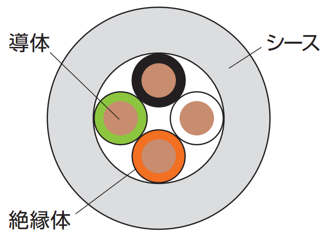
| 導体 | すずめっき軟銅撚り線 |
|---|---|
| 絶縁体 | 特殊エラストマー |
| シールド | すずめっき軟銅線 編組 |
| シース | 耐油性PVC (黒) |
| シールド有無 | 最小曲げ半径 |
|---|---|
| シールドなし | ケーブル外径の6倍以上 |
| シールドあり | ケーブル外径の8倍以上 |
| 導体 | 心線径 mm | 心数 | シールドなし | シールドあり | 許容電流注) A (30℃) |
||||||||||
|---|---|---|---|---|---|---|---|---|---|---|---|---|---|---|---|
| SQ mm2 |
AWG サイズ |
構成 | No. | 外径 mm |
概算質量 kg/km |
概算質量 kg/m |
最小曲げ R 外径×6倍 |
No. | 外径 mm |
概算質量 kg/km |
概算質量 kg/m |
最小曲げ R 外径×8倍 |
|||
| 0.5 | 21 | 100/0.08 | 1.52 | 2 | P1 | 5.3 | 34 | 0.034 | 32 | P35 | 5.7 | 45 | 0.045 | 46 | 9.2 |
| 3 | P2 | 5.5 | 41 | 0.041 | 33 | P36 | 5.9 | 53 | 0.053 | 48 | 8.0 | ||||
| 4 | P3 | 5.9 | 49 | 0.049 | 36 | P37 | 6.3 | 61 | 0.061 | 51 | 7.2 | ||||
| 5 | P4 | 6.3 | 58 | 0.058 | 38 | P38 | 6.7 | 72 | 0.072 | 54 | 6.7 | ||||
| 6 | P5 | 6.8 | 66 | 0.066 | 41 | P39 | 7.2 | 83 | 0.083 | 58 | 6.2 | ||||
| 8 | P6 | 8.0 | 90 | 0.090 | 48 | P40 | 8.4 | 110 | 0.110 | 68 | 5.6 | ||||
| 10 | P7 | 8.9 | 110 | 0.110 | 54 | - | 5.1 | ||||||||
| 0.75 | 19 | 150/0.08 | 1.73 | 2 | P8 | 5.7 | 41 | 0.041 | 35 | P41 | 6.1 | 53 | 0.053 | 49 | 12.0 |
| 3 | P9 | 5.9 | 51 | 0.051 | 36 | P42 | 6.3 | 62 | 0.062 | 51 | 10.5 | ||||
| 4 | P10 | 6.4 | 63 | 0.063 | 39 | P43 | 6.8 | 75 | 0.075 | 55 | 9.4 | ||||
| 6 | P11 | 7.4 | 87 | 0.087 | 45 | P44 | 7.8 | 105 | 0.105 | 63 | 8.1 | ||||
| 8 | P12 | 8.8 | 120 | 0.120 | 53 | P45 | 9.3 | 145 | 0.145 | 75 | 7.3 | ||||
| 10 | P13 | 9.7 | 145 | 0.145 | 59 | - | 6.7 | ||||||||
| 1.25 | 17 | 7/36/0.08 | 2.2 | 2 | P14 | 6.6 | 58 | 0.058 | 40 | P46 | 7.0 | 72 | 0.072 | 56 | 17.3 |
| 3 | P15 | 7.0 | 75 | 0.075 | 42 | P47 | 7.4 | 89 | 0.089 | 60 | 15.1 | ||||
| 4 | P16 | 7.5 | 92 | 0.092 | 45 | P48 | 7.9 | 110 | 0.110 | 64 | 13.5 | ||||
| 6 | P17 | 8.8 | 130 | 0.130 | 53 | P49 | 9.3 | 155 | 0.155 | 75 | 11.7 | ||||
| 2 | 15 | 7/57/0.08 | 2.6 | 2 | P20 | 7.4 | 79 | 0.079 | 45 | P51 | 7.8 | 94 | 0.094 | 63 | 23.6 |
| 3 | P21 | 7.8 | 105 | 0.105 | 47 | P52 | 8.2 | 120 | 0.120 | 66 | 20.6 | ||||
| 4 | P22 | 8.5 | 130 | 0.130 | 51 | P53 | 9.0 | 155 | 0.155 | 72 | 18.4 | ||||
| 6 | P23 | 10.0 | 185 | 0.185 | 60 | - | 15.9 | ||||||||
| 3.5 | 12 | 7/64/0.1 | 3.4 | 2 | P26 | 9.3 | 125 | 0.125 | 56 | P56 | 9.8 | 155 | 0.155 | 79 | 35.5 |
| 3 | P27 | 9.8 | 165 | 0.165 | 59 | - | 30.9 | ||||||||
注)許容電流は、保証値ではなく参考値です。
断面図(例)
シールドなし
シールドあり
絶縁体識別
| 心線番号 | 絶縁体色 |
|---|---|
| 1 | 黒 |
| 2 | 白 |
| 3 | 赤 |
| 4 | 緑 |
| 5 | 黄 |
| 6 | 茶 |
| 7 | 青 |
| 8 | 灰 |
| 9 | 橙 |
| 10 | 紫 |
エア配管用チューブ
| No. | 仕様 | 構成 | |||||||||||||
|---|---|---|---|---|---|---|---|---|---|---|---|---|---|---|---|
| 外径 mm | 内径 mm | 最高使用圧力 MPa | 材質 | 色 | |||||||||||
| T1 | 4.0 | 2.5 | 0.8 (20℃) | ポリウレタン | 黒, 黄, 青, 緑, 透明, 白 | ||||||||||
| T2 | 6.0 | 4.0 | 0.8 (20℃) | ポリウレタン | 黒, 黄, 青, 緑, 透明, 白 | ||||||||||
| T3 | 8.0 | 5.0 | 0.8 (20℃) | ポリウレタン | 黒, 黄, 青, 緑, 透明, 白 | ||||||||||
| T4 | 10.0 | 6.5 | 0.8 (20℃) | ポリウレタン | 黒, 黄, 青, 緑, 透明, 白 | ||||||||||
ケーブル・チューブの注意事項
フラットベヤは隣り合う支持物同士を溶着するため、下記注意事項がございます。
材質
溶着が可能なケーブル外皮材質およびチューブ材質は、PVCおよびポリウレタンのみです。
上記材質以外をご希望の場合は、当社までお問合せください。
外径差
隣接するケーブル・チューブの許容外径差の目安は、外径の小さい方に対して30%以内です。それを超える外径差が生じる場合は、ダミーチューブの使用をご提案することがございます。
[クリックで拡大]
設置手順・設置方法
お問合せシート
ホームページからのお問い合わせ/資料請求
製品お問い合わせ
各製品へのお問い合わせ及び製品カタログ・資料請求はこちらより承っております。
ご利用の際は当サイトの会員登録をお願いします。
【お問い合わせ】 |
【資料請求】 |
|---|
本製品を日本国外で購入される場合には、下記リンクにある最寄りの海外拠点までお問い合わせください。
各種証明書の発行について
一部の証明書は弊社製造番号と紐づけて発行しております。
以下についてはご購入先を通じてご依頼ください。
・該非判定書
・EAR判定書
・原産地証明書
見積依頼、納期確認について
弊社では直接販売をしておりません。
購入価格・納期に関するお問い合わせはお取引のある商社様を通じてご確認ください。
購入先をお探しのお客様は取扱販売店一覧をご覧ください。
お問い合わせ窓口
製品窓口
| ケーブルベヤ | TEL : 0120-251-664 | FAX : 0120-251-665 |
|---|
月曜日~金曜日 9:00~12:00 / 13:00~17:00
(祝日・弊社休業日を除く)
