クリーンベヤ®主要諸元
■クリーンルーム内での使用に最適です。
■使用条件に応じた専用のケーブルやチューブを組み込んで提供します。
カタログ・取扱説明書
材質
| ポッド | フッ素樹脂(ePTFE) | ||||
|---|---|---|---|---|---|
| ケーブル | 導体 | すずめっき軟銅線 あるいは 軟銅線 | |||
| 絶縁体 | フッ素樹脂(FEP, ETFE, PFA) あるいは ポリエステル系熱可塑性エラストマー(TPEE) |
||||
| バインダー | フッ素樹脂(ePTFE) | ||||
| シールド | すずめっき軟銅線 | ||||
| シース | PVC LF (鉛フリー) | ||||
| サポートメンバ | エンプラ | ||||
| クランプ | アルミニウム | ||||
| スペーサ | エンプラ | ||||
| ポッド支持用アクセサリ | PVC | ||||
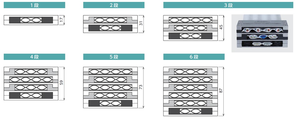
| 最大移動ストローク 注)1 | サポートメンバ 屈曲半径 R40 ・・・ 1600mm | ||||||
|---|---|---|---|---|---|---|---|
| サポートメンバ 屈曲半径 R70 ・・・ 2200mm | |||||||
| サポートメンバ 屈曲半径 R100 ・・・ 2800mm | |||||||
| サポートメンバ 屈曲半径 R130 ・・・ 2800mm | |||||||
| 最大移動速度 | 2m/sec | ||||||
| 最大加速度 | 4G | ||||||
| 使用温度範囲 | -10℃~80℃ | ||||||
| 最小・最大ケーブル・チューブ外径 | 3~10mm | ||||||
注) 1.支持物質量0.4kg/m時。
2.サポートメンバ屈曲半径とクリーンベヤ設置時の屈曲半径は異なる場合があります。
選定
クリーンベヤは、すべてメーカ仕様選定商品です。お問合せシートに使用条件をご記入いただき、当社まで送付ください。
当社にて仕様を選定します。
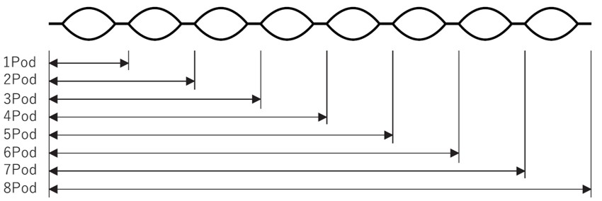
| ポッド数 | ポッド厚さ 注) mm |
ポッド幅 注) mm |
連結幅 注) mm |
全体幅 mm |
|---|---|---|---|---|
| 1Pod | 1 | 19 | 2.3 | 23.6 |
| 2Pod | 44.9 | |||
| 3Pod | 66.2 | |||
| 4Pod | 87.5 | |||
| 5Pod | 108.8 | |||
| 6Pod | 130.1 | |||
| 7Pod | 151.4 | |||
| 8Pod | 172.7 |
| ケーブル・チューブ外径 | 最大収納本数/Pod | 収納イメージ |
|---|---|---|
| 外径 ≦ Φ4.0 | 3 | 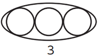 |
| Φ4.0 < 外径 ≦ Φ6.3 | 2 | 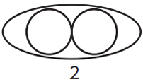 |
| Φ6.3 < 外径 ≦ Φ10 | 1 | 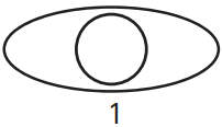 |
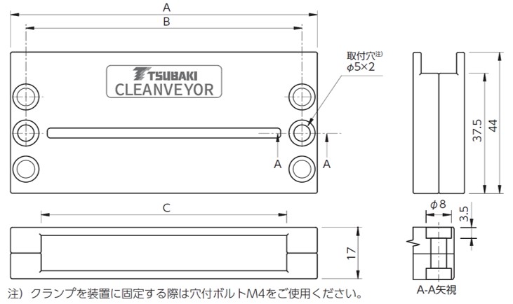
| クランプ仕様 | A mm |
B mm |
C mm |
|---|---|---|---|
| 2Pod用 | 57.2 | 47.7 | 38.2 |
| 3Pod用 | 76.3 | 66.8 | 57.3 |
| 4Pod用 | 95.4 | 85.9 | 76.4 |
| 5Pod用 | 114.5 | 105.0 | 95.5 |
| 6Pod用 | 133.6 | 124.1 | 114.6 |
| 7Pod用 | 152.7 | 143.2 | 133.7 |
| 8Pod用 | 171.8 | 162.3 | 152.8 |
ケーブル・エア配管用チューブ
300V定格ケーブル
| UL STYLE No. | 2464 |
|---|---|
| 定格温度 ℃ | 80 |
| 定格電圧 V | 300 |
| 使用温度範囲 ℃ | -10~80 |
| 導体 | すずめっき軟銅撚り線 |
|---|---|
| 絶縁体 | 特殊エラストマー |
| シールド | すずめっき軟銅線 編組 |
| シース | 耐油性PVC (黒) |
| シールド有無 | 最小曲げ半径 |
|---|---|
| シールドなし | ケーブル外径の6倍以上 |
| シールドあり | ケーブル外径の8倍以上 |
| 導体 | 心線径 mm | 対数 | シールドなし | シールドあり | 許容電流 注) A (30℃) |
||||||||||
|---|---|---|---|---|---|---|---|---|---|---|---|---|---|---|---|
| SQ mm2 |
AWG サイズ |
構成 | No. | 外径 mm |
概算質量 kg/km |
概算質量 kg/m |
最小曲げ R 外径×6倍 |
No. | 外径 mm |
概算質量 kg/km |
概算質量 kg/m |
最小曲げ R 外径×8倍 |
|||
| 0.1 | 28 | 49/0.05 | 0.74 | 1 | S1 | 3.3 | 13 | 0.013 | 20 | S32 | 3.8 | 21 | 0.021 | 31 | 2.4 |
| 2 | S2 | 4.4 | 20 | 0.020 | 27 | S33 | 4.8 | 30 | 0.030 | 39 | 1.8 | ||||
| 3 | S3 | 4.7 | 23 | 0.023 | 29 | S34 | 5.1 | 34 | 0.034 | 41 | 1.6 | ||||
| 4 | S4 | 5.0 | 27 | 0.027 | 30 | S35 | 5.4 | 38 | 0.038 | 44 | 1.4 | ||||
| 5 | S5 | 5.3 | 32 | 0.032 | 32 | S36 | 5.7 | 43 | 0.043 | 46 | 1.3 | ||||
| 6 | S6 | 5.6 | 36 | 0.036 | 34 | S37 | 6.0 | 48 | 0.048 | 48 | 1.2 | ||||
| 7 | S7 | 5.6 | 39 | 0.039 | 34 | S38 | 6.0 | 50 | 0.050 | 48 | 1.2 | ||||
| 8 | S8 | 6.0 | 43 | 0.043 | 36 | S39 | 6.4 | 56 | 0.056 | 52 | 1.1 | ||||
| 10 | S9 | 6.6 | 52 | 0.052 | 40 | S40 | 7.0 | 66 | 0.066 | 56 | 1.0 | ||||
| 0.2 | 25 | 102/0.05 | 0.93 | 1 | S10 | 3.7 | 17 | 0.017 | 23 | S41 | 4.2 | 25 | 0.025 | 34 | 3.8 |
| 2 | S11 | 5.0 | 27 | 0.027 | 30 | S42 | 5.4 | 37 | 0.037 | 44 | 3.0 | ||||
| 3 | S12 | 5.3 | 34 | 0.034 | 32 | S43 | 5.7 | 45 | 0.045 | 46 | 2.6 | ||||
| 4 | S13 | 5.7 | 39 | 0.039 | 35 | S44 | 6.3 | 51 | 0.051 | 51 | 2.3 | ||||
| 5 | S14 | 6.1 | 47 | 0.047 | 37 | S45 | 6.5 | 60 | 0.060 | 52 | 2.1 | ||||
| 6 | S15 | 6.6 | 54 | 0.054 | 40 | S46 | 7.1 | 69 | 0.069 | 57 | 2.0 | ||||
| 7 | S16 | 6.6 | 58 | 0.058 | 40 | S47 | 7.1 | 73 | 0.073 | 57 | 1.9 | ||||
| 8 | S17 | 7.1 | 65 | 0.065 | 43 | S48 | 7.6 | 80 | 0.080 | 61 | 1.8 | ||||
| 10 | S18 | 7.8 | 80 | 0.080 | 47 | S49 | 8.2 | 97 | 0.097 | 66 | 1.7 | ||||
| 0.3 | 23 | 108/0.06 | 1.09 | 1 | S19 | 4.0 | 20 | 0.020 | 24 | S50 | 4.4 | 28 | 0.028 | 36 | 5.2 |
| 2 | S20 | 5.5 | 36 | 0.036 | 33 | S51 | 5.9 | 44 | 0.044 | 48 | 4.0 | ||||
| 3 | S21 | 5.9 | 42 | 0.042 | 36 | S52 | 6.4 | 54 | 0.054 | 52 | 3.5 | ||||
| 4 | S22 | 6.3 | 51 | 0.051 | 38 | S53 | 6.7 | 64 | 0.064 | 54 | 3.2 | ||||
| 5 | S23 | 6.9 | 61 | 0.061 | 42 | S54 | 7.3 | 76 | 0.076 | 59 | 2.9 | ||||
| 6 | S24 | 7.4 | 72 | 0.072 | 45 | S55 | 7.8 | 87 | 0.087 | 63 | 2.7 | ||||
| 7 | S25 | 7.4 | 78 | 0.078 | 45 | S56 | 7.8 | 94 | 0.094 | 63 | 2.5 | ||||
| 8 | S26 | 8.0 | 88 | 0.088 | 48 | S57 | 8.4 | 105 | 0.105 | 68 | 2.4 | ||||
| 10 | S27 | 8.8 | 110 | 0.110 | 53 | S58 | 9.2 | 130 | 0.130 | 74 | 2.3 | ||||
| 0.5 | 21 | 177/0.06 | 1.36 | 1 | S28 | 4.6 | 26 | 0.026 | 28 | S59 | 5.0 | 37 | 0.037 | 30 | 7.7 |
| 2 | S29 | 6.4 | 51 | 0.051 | 39 | S60 | 6.8 | 67 | 0.067 | 41 | 5.8 | ||||
| 3 | S30 | 6.9 | 64 | 0.064 | 42 | S61 | 7.3 | 82 | 0.082 | 44 | 4.9 | ||||
| 4 | S31 | 7.5 | 75 | 0.075 | 45 | S62 | 7.9 | 94 | 0.094 | 48 | 4.7 | ||||
注)許容電流は、保証値ではなく参考値です。
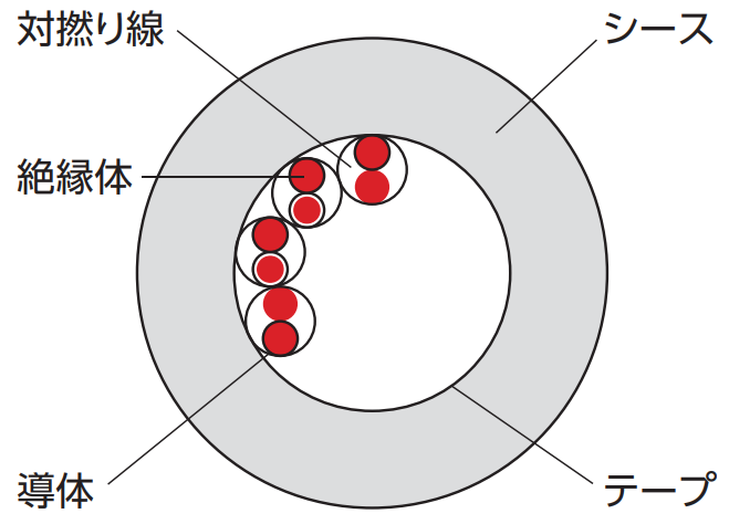
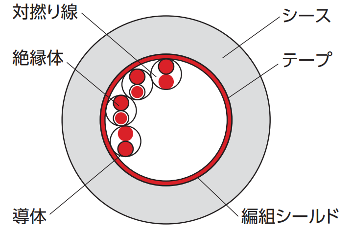
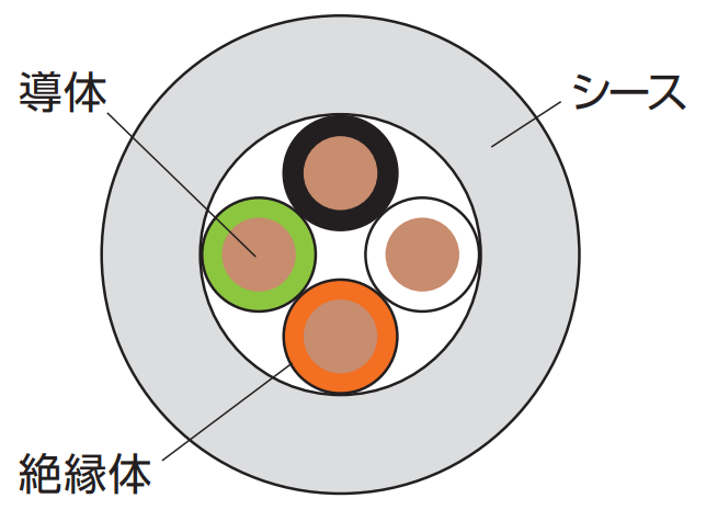
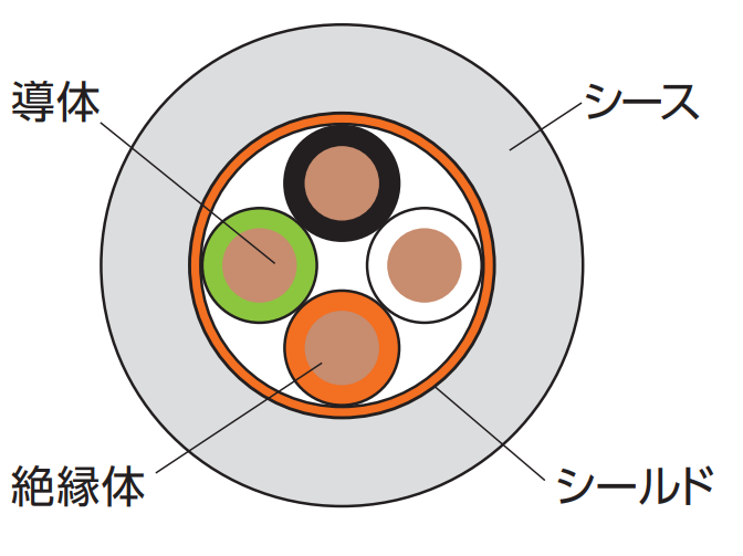
断面図(例)
シールドなし
シールドあり
絶縁体識別
| 対番号 | 絶縁体色 | |
|---|---|---|
| 第1種心線 | 第2種心線 | |
| 1 | 青 | 白 |
| 2 | 黄 | 紫 |
| 3 | 緑 | 黒 |
| 4 | 赤 | 灰 |
| 5 | 紫 | 橙 |
| 対番号 | 絶縁体色 | |
|---|---|---|
| 第1種心線 | 第2種心線 | |
| 6 | 青 | 茶 |
| 7 | 黄 | 黒 |
| 8 | 緑 | 灰 |
| 9 | 赤 | 橙 |
| 10 | 紫 | 白 |
600V定格ケーブル
| UL STYLE No. | 2586 |
|---|---|
| 定格温度 ℃ | 105 |
| 定格電圧 V | 600 |
| 使用温度範囲 ℃ | -10~105 |
| 導体 | すずめっき軟銅撚り線 |
|---|---|
| 絶縁体 | 特殊エラストマー |
| シールド | すずめっき軟銅線 編組 |
| シース | 耐油性PVC (黒) |
| シールド有無 | 最小曲げ半径 |
|---|---|
| シールドなし | ケーブル外径の6倍以上 |
| シールドあり | ケーブル外径の8倍以上 |
| 導体 | 心線径 mm | 心数 | シールドなし | シールドあり | 許容電流注) A (30℃) |
||||||||||
|---|---|---|---|---|---|---|---|---|---|---|---|---|---|---|---|
| SQ mm2 |
AWG サイズ |
構成 | No. | 外径 mm |
概算質量 kg/km |
概算質量 kg/m |
最小曲げ R 外径×6倍 |
No. | 外径 mm |
概算質量 kg/km |
概算質量 kg/m |
最小曲げ R 外径×8倍 |
|||
| 0.5 | 21 | 100/0.08 | 1.52 | 2 | P1 | 5.3 | 34 | 0.034 | 32 | P35 | 5.7 | 45 | 0.045 | 46 | 9.2 |
| 3 | P2 | 5.5 | 41 | 0.041 | 33 | P36 | 5.9 | 53 | 0.053 | 48 | 8.0 | ||||
| 4 | P3 | 5.9 | 49 | 0.049 | 36 | P37 | 6.3 | 61 | 0.061 | 51 | 7.2 | ||||
| 5 | P4 | 6.3 | 58 | 0.058 | 38 | P38 | 6.7 | 72 | 0.072 | 54 | 6.7 | ||||
| 6 | P5 | 6.8 | 66 | 0.066 | 41 | P39 | 7.2 | 83 | 0.083 | 58 | 6.2 | ||||
| 8 | P6 | 8.0 | 90 | 0.090 | 48 | P40 | 8.4 | 110 | 0.110 | 68 | 5.6 | ||||
| 10 | P7 | 8.9 | 110 | 0.110 | 54 | - | 5.1 | ||||||||
| 0.75 | 19 | 150/0.08 | 1.73 | 2 | P8 | 5.7 | 41 | 0.041 | 35 | P41 | 6.1 | 53 | 0.053 | 49 | 12.0 |
| 3 | P9 | 5.9 | 51 | 0.051 | 36 | P42 | 6.3 | 62 | 0.062 | 51 | 10.5 | ||||
| 4 | P10 | 6.4 | 63 | 0.063 | 39 | P43 | 6.8 | 75 | 0.075 | 55 | 9.4 | ||||
| 6 | P11 | 7.4 | 87 | 0.087 | 45 | P44 | 7.8 | 105 | 0.105 | 63 | 8.1 | ||||
| 8 | P12 | 8.8 | 120 | 0.120 | 53 | P45 | 9.3 | 145 | 0.145 | 75 | 7.3 | ||||
| 10 | P13 | 9.7 | 145 | 0.145 | 59 | - | 6.7 | ||||||||
| 1.25 | 17 | 7/36/0.08 | 2.2 | 2 | P14 | 6.6 | 58 | 0.058 | 40 | P46 | 7.0 | 72 | 0.072 | 56 | 17.3 |
| 3 | P15 | 7.0 | 75 | 0.075 | 42 | P47 | 7.4 | 89 | 0.089 | 60 | 15.1 | ||||
| 4 | P16 | 7.5 | 92 | 0.092 | 45 | P48 | 7.9 | 110 | 0.110 | 64 | 13.5 | ||||
| 6 | P17 | 8.8 | 130 | 0.130 | 53 | P49 | 9.3 | 155 | 0.155 | 75 | 11.7 | ||||
| 2 | 15 | 7/57/0.08 | 2.6 | 2 | P20 | 7.4 | 79 | 0.079 | 45 | P51 | 7.8 | 94 | 0.094 | 63 | 23.6 |
| 3 | P21 | 7.8 | 105 | 0.105 | 47 | P52 | 8.2 | 120 | 0.120 | 66 | 20.6 | ||||
| 4 | P22 | 8.5 | 130 | 0.130 | 51 | P53 | 9.0 | 155 | 0.155 | 72 | 18.4 | ||||
| 6 | P23 | 10.0 | 185 | 0.185 | 60 | - | 15.9 | ||||||||
| 3.5 | 12 | 7/64/0.1 | 3.4 | 2 | P26 | 9.3 | 125 | 0.125 | 56 | P56 | 9.8 | 155 | 0.155 | 79 | 35.5 |
| 3 | P27 | 9.8 | 165 | 0.165 | 59 | - | 30.9 | ||||||||
注)許容電流は、保証値ではなく参考値です。
断面図(例)
シールドなし
シールドあり
絶縁体識別
| 心線番号 | 絶縁体色 |
|---|---|
| 1 | 黒 |
| 2 | 白 |
| 3 | 赤 |
| 4 | 緑 |
| 5 | 黄 |
| 6 | 茶 |
| 7 | 青 |
| 8 | 灰 |
| 9 | 橙 |
| 10 | 紫 |
エア配管用チューブ
| No. | 仕様 | 構成 | |||||||||||||
|---|---|---|---|---|---|---|---|---|---|---|---|---|---|---|---|
| 外径 mm | 内径 mm | 最高使用圧力 MPa | 材質 | 色 | |||||||||||
| T1 | 4.0 | 2.5 | 0.8 (20℃) | ポリウレタン | 黒, 黄, 青, 緑, 透明, 白 | ||||||||||
| T2 | 6.0 | 4.0 | 0.8 (20℃) | ポリウレタン | 黒, 黄, 青, 緑, 透明, 白 | ||||||||||
| T3 | 8.0 | 5.0 | 0.8 (20℃) | ポリウレタン | 黒, 黄, 青, 緑, 透明, 白 | ||||||||||
| T4 | 10.0 | 6.5 | 0.8 (20℃) | ポリウレタン | 黒, 黄, 青, 緑, 透明, 白 | ||||||||||
設置手順・設置方法
お問合せシート
ホームページからのお問い合わせ/資料請求
製品お問い合わせ
各製品へのお問い合わせ及び製品カタログ・資料請求はこちらより承っております。
ご利用の際は当サイトの会員登録をお願いします。
【お問い合わせ】 |
【資料請求】 |
|---|
本製品を日本国外で購入される場合には、下記リンクにある最寄りの海外拠点までお問い合わせください。
各種証明書の発行について
一部の証明書は弊社製造番号と紐づけて発行しております。
以下についてはご購入先を通じてご依頼ください。
・該非判定書
・EAR判定書
・原産地証明書
見積依頼、納期確認について
弊社では直接販売をしておりません。
購入価格・納期に関するお問い合わせはお取引のある商社様を通じてご確認ください。
購入先をお探しのお客様は取扱販売店一覧をご覧ください。
お問い合わせ窓口
製品窓口
| ケーブルベヤ | TEL : 0120-251-664 | FAX : 0120-251-665 |
|---|
月曜日~金曜日 9:00~12:00 / 13:00~17:00
(祝日・弊社休業日を除く)


