Cable Carrier Accessories Guide Channels for Gliding Arrangement Major Specifications
TKP58H39-30W50・with gliding shoe
Construction
[Click to enlarge ]
CAD data in DXF format
See below
(Click here for a list of all DXF files )
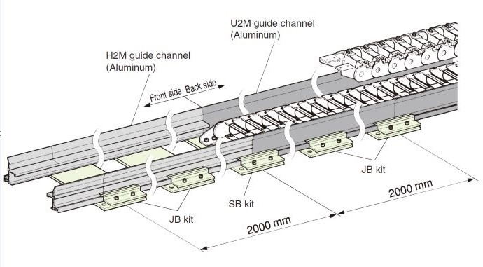
This part is composed of two types of guide channels: the H2M guide channel (front side) and U2M guide channel (back side). This part can be used alone, however, there are two fastening bases (SB kit and JB kit) that can be used to easily install guide channels to the mounting surface quickly and precisely. Guide channel clamps (RCL06) can be used to easily align guide channel joints at connections. Guide channels and guide channel clamps can also be used alone.
Notes
1.Guide channels are made of aluminum, anodized, and painted silver.
2.Fasten guide channels every meter.
| Applicable | Guide channel model number | Drawing data | Standard Price | Delivery |
|---|---|---|---|---|
| H2M guide channel (front side) | TKP58H39-H2M | DXF | Contact us for details. | Contact us for details. |
| U2M guide channel (back side) | TKP58H39-U2M | DXF | Contact us for details. | Contact us for details. |
Catalogs ・Instruction Manuals
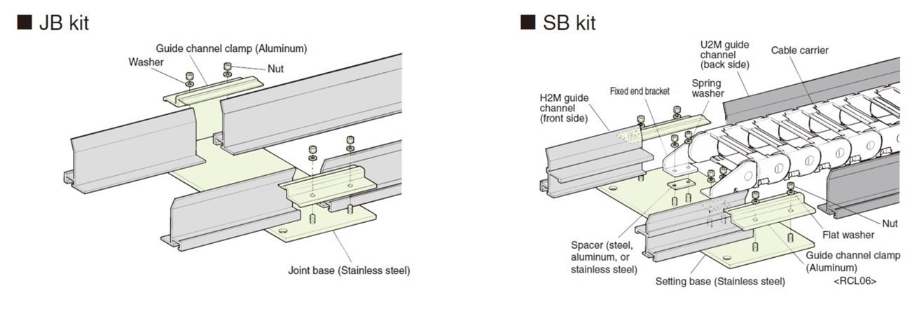
Fastening base
[Click to enlarge ]
Notes
1.Cable carriers and fixed end brackets are sold separately.
2.Setting base has a structure to which the fixed end bracket of cable carrier can be installed. Other dimensions are the same as joint base.
3.Guide channels will wear down quickly when a travel speed is high. Contact a Tsubaki representative for further information.
4.Guide channels will also wear down quickly in environments where dust, debris, or other matter is allowed to accumulate.
5.Do not install and use outdoors.
6.Guide channels will shrink and expand when used in locations with large temperature differences. Allow sufficient leeway at guide channel joints for shrinking and expansion.
| Applicable | Fastening base model number | Drawing data | Standard Price | Delivery |
|---|---|---|---|---|
| JB kit | TKP58H39W50GS-JB | DXF | Contact us for details. | Contact us for details. |
| SB kit | TKP58H39W50GS-SB | DXF | Contact us for details. | Contact us for details. |
| Model No. | Standard Price | Delivery |
|---|---|---|
| RCL06 | Contact us for details. | Contact us for details. |
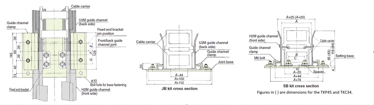
Dimension drawings
[Click to enlarge ]
| A | B | C | D | E | F | G |
|---|---|---|---|---|---|---|
| 81 | 37 | M6 | 10 | 21 | 10.5 | 24 |
Operating range
Operating range of aluminum guide channels
1.Maximum travel speed: 60 m/min or less (as a countermeasure for wear)
2.Not for outdoor use.
3.Clearance is required between guide channels in high-temperature environments because the entire length will change due to the temperature.
Linear coefficient of expansion: 2.4 × 10⁻⁵ (20°C to 100°C)
Amount of change = Entire length (mm) × Temperature difference (°C) × 0.000024
Calculating the guide channel length
When fixed end is at the center of the length
・H guide channel length = S/2 - E
・U guide channel length = S/2 + K + R + E + 100
E:Refer to installation dimensions table R:Cable carrier bending radius S:Stroke 100:Guide channel leeway length K:Leeway length
・Guide channels have a standard length of 2000 mm. Order rails in increments of 2000 mm and give the calculated result some leeway.
Contact Information
Online Inquiries
For inquiries in English, visit the Inquiries page on our Tsubaki Group website.
When purchasing this product outside of Japan, please contact nearest overseas office using the link below.
